CRGO steel is imported in the form of mother coils from reputed steel producers in USA, Japan, Korea, Germany, China, Russia etc. Each coil conforms to the specifications of Bureau of Indian Standards of quality (IS 3024). Each lot of raw material is accompanied with Mill Test Certificate (MTC) and other relevant chain of documents that can be produced at customer’s request.
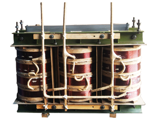
The core of the transformer is used to carry magnetic flux from primary winding to secondary winding. In this process some unwanted current (Eddy currents) are developed in the core, which is responsible for heat losses in the core. To increase the efficiency of the transformer it is necessary that there should be maximum flux linkage from primary to the secondary and losses minimized. This is done by using CRGO Lamination for construction of the core
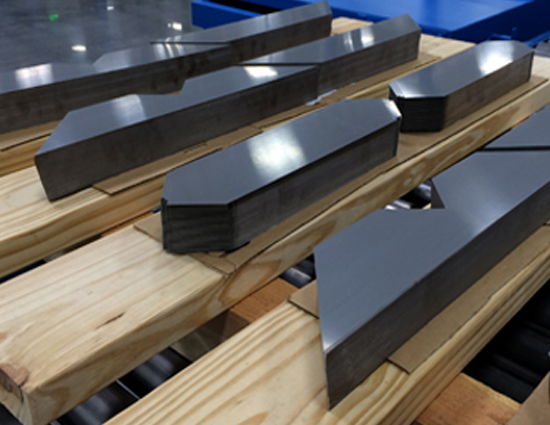
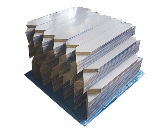
Processing of Transformer lamination requires high degree of precision for which highly customized CNC machine are required. Equipped with 3 automatic CNC cut to length machines and 2 slitting lines, we can process 3000MT CRGO per annum at ease. Our CNC Cut to Length machines are able to process lamination in various shapes and sizes with 90°/75°/45° angle cutting. The lamination can be cut to different dimension ranging from 25 mm to 1050 mm width and 100 mm to 5000 mm
We can process transformer lamination in the below form :
Conventional Designs
Horizontal Step Lap
Vertical Step Lap 789yu
Reactor Cor
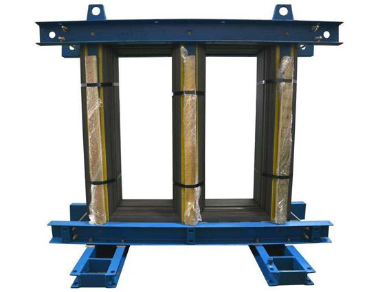
We manufacture complete CRGO Core Assembly for the Distribution and Power transformers of upto 20 MVA. The Core Assembly is extensively tested for no load losses while they are packed with utmost care and are ready for insertion of LV and HV coils. By choosing our built cores, it facilates in labour cost and no wastage of material. With the latest testing facility and modern infrastructure, we can achieve desirable No-Load Losses with limited excitation current and over-saturation
General Physical and Mechanical Properties of CRGO Steel |
|
| Density | 7.65 g/cm3 |
| Thickness of sheet | 0.23 – 0.35 mm |
| Silicon content | 3-4 % |
| Yield Point (relative to rolling direction) | 0 degrees • 330 N/mm2 90 degrees • 355 N/mm2 |
| Tensile strength | 0 degrees • 348 N/mm2 90 degrees • 412 N/mm2 |
| Elongation | 0 degrees • 11% 90 degrees • 31% |
| Number of bends | 0 degrees • 21 90 degrees • 15 |
| Hardness (HV) | 204 |
| Stacking factor | > 96% |
CLASSIFICATION OF CRGO BY GRADE |
||||
Grade (Conventional Nomenclature) | Thickness (mm) | Max. Core loss (W/kg) 50Hz | ||
| @1.5T | @1.7T | |||
| 23HP85 | 23ZDKH | 0.23 | 0.6 | 0.85 |
| 23HP90 | 23M0-H | 0.23 | 0.64 | 0.9 |
| 23HP95 | 23M0-H | 0.23 | 0.66 | 0.95 |
| 23HP100 | 23M0-H | 0.23 | 0.68 | 1 |
| 23CG110 | M3 | 0.23 | 0.7 | 1.1 |
| 27HP95 | 27ZDKH | 0.27 | 0.66 | 0.95 |
| 27HP100 | 27M0-H | 0.27 | 0.7 | 1 |
| 27HP110 | 27M0-H | 0.27 | 0.78 | 1.1 |
| 27CG120 | M4 | 0.27 | 0.85 | 1.2 |
| 27CG130 | M4 | 0.27 | 0.9 | 1.3 |
| 30HP105 | 30M0-H | 0.3 | 0.75 | 1.05 |
| 30CG130 | M5 | 0.3 | 0.9 | 1.3 |
| 30CG140 | M5 | 0.3 | 0.95 | 1.4 |
| TOLERANCE CHART | ||
| Attribute | Attribute Range | Tolerance |
| Width | 0 – 100 mm | +0.00 / -0.15 mm |
| 100 mm – 230 mm | +0.00 / -0.20 mm | |
| 230 mm – 400 mm | +0.00 / -0.30 mm | |
| 400 mm – 750 mm | +0.00 / -0.50 mm | |
| Length | 0 – 350 mm | +0.00 / -0.30 mm |
| 350 mm – 1,000 mm | +0.00 / -0.60 mm | |
| 1,000 mm – 2,000 mm | +0.00 / -1.00 mm | |
| 2,000 mm – 3,000 mm | +0.00 / -1.50 mm | |
| 3,000 mm – 4,000 mm | +0.00 / -2.00 mm | |
| Thickness | 0.23 – 0.27 mm | +/- 0.025 mm |
| 0.30 – 0.35 mm | +/- 0.030 mm | |
| Mitering Angle | 45 degrees | +/- 5 minutes |
| Burr Height | 0.18 – 0.23 mm | 10 microns |
| 0.23 – 0.30 mm | 15 microns | |
| 0.30 – 0.35 mm | 20 microns | |
| Wave Factor | Material width > 150mm | Max. 1.5% of width |
| Flatness deviation | ||
| Edge Camber | Material width > 150mm | Max. 0.8 mm for 1.5m |
| Hole Dimension | Up to 34 mm | +/- 0.15 mm |


